Realtime Monitoring Of A Sensor Attached To An Arduino
Created on: 2016-02-06 05:00:00 -0500
Categories: ArduinoRaspberry PiWeb Development
Based on my experience, I often find that putting together a prototype to demonstrate an idea helps communicating with clients. Having worked in both the sensors area network field and Internet of Things sector, I often utilize the Arduino and Raspberry Pi to quickly create interactive demonstrations to refine the client’s requirements. Then we can work towards creating a final product. In this tutorial, I will go over one technique I use to refine a client’s requirements for a system.
In this tutorial, we will combine the Raspberry Pi and Arduino to help send data from a potentiometer. The potentiometer could be swapped by any sensor that output an analog signal. We will be using the Google Chrome browser on a desktop PC to help display that changes made when we turn the potentiometer knob.
Setup
We will assume that you have the latest Rasbian OS installed on the Raspberry Pi Model 2 B. For this tutorial we are using:
RASPBIAN JESSIE
- Version: November 2015
- Release date:2015-11-21
First we will start with simply making the potentiometer circuit on the Arduino Uno board. The diagram below shows the wiring that we will use.
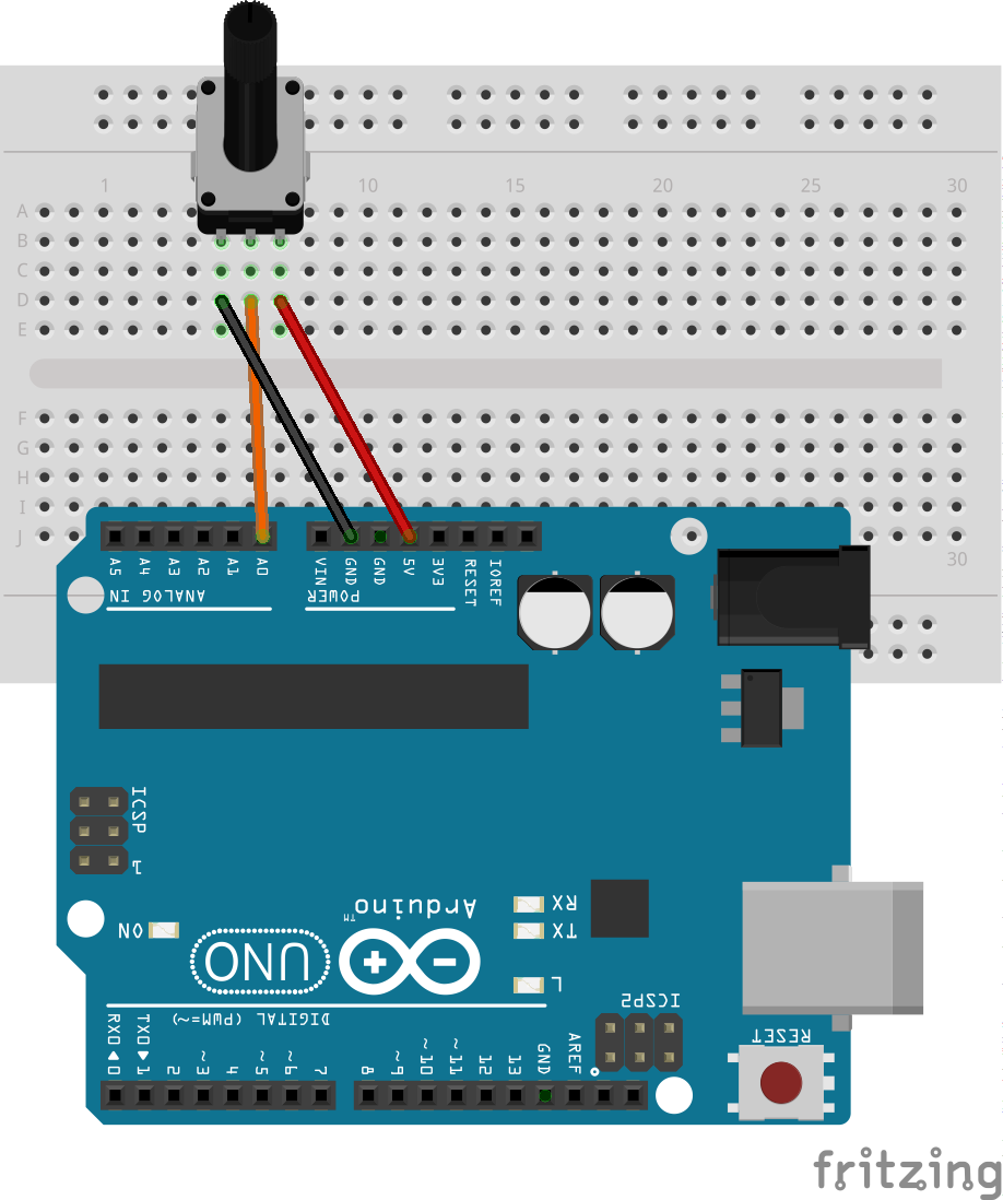
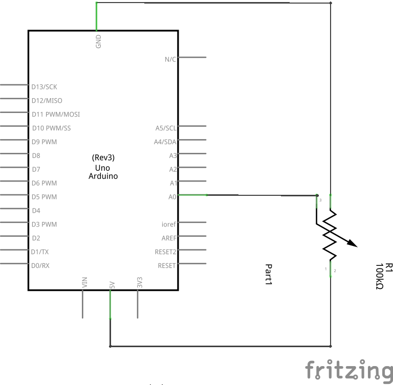
Essentially, we will attach +5V to the first pin on the potentiometer and attach the third pin of the potentiometer to the ground (GND). The middle leg of the potentiometer will be attached to A0 port on the Arduino port.
The code that will be loaded onto the Arduino is as follows:
void setup() {
        Serial.begin(9600);
}

void loop() {
        int value = analogRead(A0);
        Serial.println(value);
        delay(1000);
}
When the Arduino runs it will read that voltage level at A0 every second and send data through the serial out to the Raspberry Pi.
On the Raspberry Pi, the Arduino USB connection will come up as /dev/ttyACM0. To speed things up we will be using the Ino application that provides a command line interface to handle the compilation and uploading of the Arduino application. Instructions on the installation can be found from Ino’s website. Or you can try entering the command:
$ sudo pip install inoAfter you can make directory to hold your arduino sketches and set up a project folder for the potentiometer code. Then using to Ino application you can compile the code and upload it to the Arduino. The default board and port for the Ino is the Arduino Uno on port /dev/ttyACM0.
$ mkdir -p ~/arduino_sketches/potentiometer
$ cd ~/arduino_sketches
$ mkdir lib
$ mkdir src
$ cd src
$ wget -O src/sketch.ino https://raw.githubusercontent.com/salimwp/arduino_sketches/master/potentiometer/src/sketch.ino
$ ino build
$ ino upload
The Arduino is now programmed and we can proceed to dealing with the software needed on the Raspberry Pi. We will now compile the arduinod application. This application simply reads any data coming from the Arduino on /dev/ttyACM0 and sends it over the TCP connection. The TCP connection will use port 8088 so we can connect it directly to our Google Chrome Extension application.
There is a Makefile that comes with the arduinod application so all you need to do is clone the arduinod from github and run make:
$ git clone https://github.com/salimwp/arduinod.git
$ make
Running the project
First we will need to start the arduinod application. To do this simply run the following command:
$ ./arduinod -h 0.0.0.0 -p 8088Once you get the ChromeGraphsTCP extension, you will need to edit the network.js file to the IP address of your Raspberry Pi. In the function initServerConnection you will see a function call:
chrome.sockets.tcp.connect(socketId, "192.168.1.2", 8088, function(connectInfo)Change the “192.168.1.2” to your Raspberry Pi. You can now load the ChromeGraphsTCP extension to see the data from the Arduino. As you move the potentiometer the gauge on the Chrome window will reflect the changes. The video below shows a quick demonstration of this tutorial.
That wraps up this tutorial. In a future tutorial, I will show how to refine this process to simplify graphing a remote sensor. There are two ways this can be done. First, we can use the GPIO headers on the Raspberry Pi to talk to a Analog-to-Digital IC, which will replace the need for the Arduino. Alternatively, we can install a network interface on the Arduino. This will allow the Arduino to communicate to a server without the need of the Raspberry Pi. Each solution has their own pros and cons. Keep checking my blogs posts or Twitter feed to see when these tutorials become available.